AB DEFENCE Platform support
Unimog U 2450 L
Explore platform information, technical systems and spare parts support.
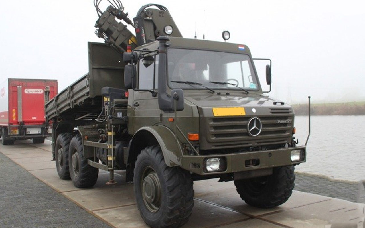
Spare parts supply for the rarest and most capable platform in the entire Series 437 programme. AB Defence maintains dedicated inventory and sourcing networks for the OM366LA intercooled powertrain, the bogie third-axle drivetrain, the PTO-driven hydraulic system, Central Tyre Inflation System (CTIS), and every mechanical assembly of the U 2450 L
Request a QuoteA Platform Unlike Any Other in the Unimog Range
Every Unimog platform covered by AB Defence shares certain engineering fundamentals: portal axles, coil spring suspension, lockable differentials, a fully synchronised gearbox. The U 2450 L has all of these. But it is in every other respect a fundamentally different machine from the 4×4 Series 437 vehicles that surround it in the catalogue.
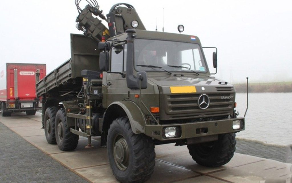
Introduced in 1995 and carrying the internal Mercedes-Benz designation 437.156, the U 2450 L was the first and only three-axle, all-wheel-drive Unimog in the heavy series programme. Amazon It was not developed as a variant of the U 2150 L. It was developed as an answer to a specific operational requirement: a wheeled platform with Unimog-class cross-country mobility, sufficient payload and towing capacity to serve as a medium recovery vehicle, and the structural robustness to operate under sustained load in austere environments without requiring tracked vehicle support assets. Nothing in the conventional military truck catalogue offered all three simultaneously. The U 2450 L did.
Production numbers were extremely limited — approximately 200 vehicles total — meaning that virtually every U 2450 L in existence today began its operational life in military service. Trucksplanet The largest single operator was the Australian Defence Force, whose 1995 contract for 55 vehicles at AUD $20.5 million represented a procurement commitment to the platform's capabilities as a direct replacement for ageing International F1 recovery vehicles. European military operators, primarily within the Bundeswehr's specialist support structure, account for most of the remaining fleet.
For spare parts suppliers, this scarcity creates a specific and serious challenge. The U 2450 L's third-axle bogie, its inter-axle drivetrain components, its CTIS system, and its OM366LA intercooled powertrain are all low-volume components with no equivalent in any other Unimog platform. AB Defence treats the U 2450 L as a programme in its own right — not as a footnote to the Series 437 catalogue — and maintains dedicated sourcing relationships for its unique component families.
Technical Specifications — Unimog U 2450 L (Series 437.156)
- Series Designation:
- Unimog 437 / 437.156
- Introduced:
- 1995 (Gaggenau production; transferred to Wörth 2002)
- Total Production:
- Approximately 200 vehicles
- Engine:
- Mercedes-Benz OM 366 LA · 5,958 cc · Inline-6 · Turbocharged & Intercooled
- Power Output:
- 177 kW / 240 hp @ 2,600 rpm
- Torque:
- 760 Nm @ 1,700 rpm
- Compression Ratio:
- 16.5:1
- Engine Specification:
- Euro II with intercooler; piston-cooled with oil spray nozzles
- Gearbox:
- UG3/65 · 8-Speed Fully Synchronised (8 forward / 8 reverse)
- Drive System:
- Part-Time 6×6 · Selectable by Driver
- Differentials:
- Front, Centre, and Rear — all lockable
- Axle Configuration:
- Three-axle bogie (6×6): 2 steering/drive front axles + rear bogie twin-axle
- Wheelbase (1st to 2nd axle):
- 3,900 mm
- Wheelbase (1st to 3rd axle):
- 5,300 mm Track Width: 1,870 mm GVM: 17,000–18,000 kg (configuration-dependent) Unladen
- Weight:
- Approximately 13,500 kg (fully equipped MRV configuration)
- Payload:
- Up to 7,000 kg Gross
- Train Weight (Braked Trailer):
- 12,000 kg towing capacity
- Length (Overall):
- 7,580 mm
- Width:
- 2,500 mm
- Height (Cab):
- 2,800 mm
- Ground Clearance:
- 495 mm
- Approach Angle:
- 47 degrees
- Departure Angle:
- 49 degrees
- Turning Radius:
- 9.25 m
- Tyres (Standard):
- 14.5R20 (military cross-country)
- Fuel Tank:
- 165 L standard / 220 L optional
- Braking:
- Disc brakes
The OM366LA — The Intercooled Engine That Defines the U 2450 L
The single most important distinction between the U 2450 L and the U 2150 L is not the additional axle. It is the engine. Where the U 2150 L uses the OM366A — turbocharged but not intercooled — the U 2450 L is fitted from the factory with the OM366LA: the same 5,958 cc inline-6 block, but with an air-to-air intercooler installed between the turbocharger compressor outlet and the intake manifold. This distinction changes the engine's performance ceiling, its thermal behaviour, and critically, its parts specification in ways that make component identification essential before any powertrain parts order is placed.
The intercooler's function is to cool the compressed charge air after it leaves the turbocharger and before it enters the combustion chamber. Cooler charge air is denser, which allows more oxygen per combustion cycle, which in turn allows a higher safe fuel delivery rate. The result is that the OM366LA achieves 177 kW / 240 hp and 760 Nm from the same block architecture that produces 125 kW / 170 hp in the non-intercooled OM366A fitted to the U 2150 L. This is not simply a recalibration; it requires different injectors (different hole count, diameter, and spray angle), a different injection pump delivery setting, and the complete intercooler system with its associated piping, clamping, and end-tank hardware.
The practical maintenance consequence is direct: OM366A injectors must not be fitted to an OM366LA engine, and vice versa. The injector nozzle specification — number of holes, orifice diameter, and spray pattern — is calibrated to the specific air-fuel ratio of each variant. Fitting the wrong nozzle specification will result in incorrect combustion, excess exhaust temperature, and accelerated injector and combustion chamber wear. AB Defence catalogues OM366A and OM366LA injection components under separate part families and requires engine variant confirmation — OM366A or OM366LA — before issuing any fuel injection system component.
The OM366LA retains the piston oil spray cooling system of the higher-power OM366A variants: oil spray nozzles direct pressurised oil to the underside of each piston crown, managing the additional thermal load of the intercooled, high-output engine. These nozzles must be included in every bottom-end inspection and are a specific maintenance item in the OM366LA service schedule.
OM366LA Engine Overhaul Components
Complete engine overhaul gasket and seal sets for the OM366LA variant — including the additional intercooler system sealing components absent from OM366A kits. Cylinder liner assemblies and piston sets to OM366LA specification. Main and big-end bearing shell sets with undersized options for reground crankshafts. Piston cooling oil spray nozzle assemblies and feed gallery hardware. Timing gear sets and front cover seals. Cylinder head bolt sets. Rocker shaft and valve train assemblies. Crankshaft front and rear main seals.
Intercooler System — OM366LA Exclusive
The intercooler is the defining external difference between the OM366A and OM366LA installations. On the U 2450 L, it is mounted in the engine bay ahead of the radiator, with inlet and outlet piping routed between the turbocharger compressor outlet and the engine intake manifold. Air-to-air intercooler core and end-tank assemblies. Charge air inlet and outlet hose sets with heavy-duty clamp hardware. Intercooler mounting bracket and anti-vibration isolator hardware. Boost pressure pipe and union assemblies. Intercooler core inspection and flow test documentation available on request for pre-overhaul assessment.
Turbocharger System
The OM366LA uses the same turbocharger family as the high-output OM366A but operates under different thermal conditions due to the intercooler's charge air cooling effect. Complete CHRA turbocharger cartridge assemblies for OM366LA applications. Oil feed banjo bolt and copper washer sealing kits. Oil scavenge return line hardware and elbow fittings. Turbocharger inlet hose and clamp assemblies from air cleaner housing. Exhaust manifold to turbine inlet gaskets and stud hardware. Wastegate actuator assemblies and boost calibration hardware.
Bosch Fuel Injection System — OM366LA Calibration
Bosch in-line injection pump elements and delivery valves calibrated to OM366LA 177 kW specification — note the higher fuel delivery setting versus OM366A. Injector nozzle assemblies to OM366LA specification: confirm hole count and spray angle before ordering, as these are not interchangeable with OM366A nozzles despite identical external appearance. Injection pump governor spring sets (RSV-type). High-pressure fuel line sets (6-cylinder complete set). Primary and secondary fuel filter elements and housing seal kits. Fuel lift pump assemblies and diaphragm kits.
Cooling System
The U 2450 L's cooling system must manage the thermal output of a 177 kW engine under sustained heavy military load, often in high-ambient-temperature environments. The radiator specification reflects this: larger core area than the U 2150 L, with correspondingly higher coolant flow requirements. Radiator core and complete assembly to OM366LA / U2450L specification. Thermostat and housing assemblies. Water pump assemblies, impeller, and mechanical seal sets. Viscous fan coupling assemblies. Complete coolant hose sets for U 2450 L engine bay routing. Coolant pressure testing cap assemblies.
Oil System
Oil pump assemblies and pressure relief valve kits. Piston cooling oil squirter feed circuit hardware — a mandatory check item during any OM366LA bottom-end overhaul. Oil cooler elements and housing seals. Crankshaft seals and sump gasket sets. Military-grade oil filter elements and housing assemblies.
The 6×6 Drivetrain — Three Axles, Five Differentials, One Unique Parts Profile
The U 2450 L's drivetrain is the engineering core that makes it operationally irreplaceable — and the primary reason its spare parts sourcing must be treated as a completely independent programme from any other Unimog platform. A 4×4 Series 437 drivetrain has two axles and two lockable differentials. The U 2450 L has three axles, a total of five differential assemblies, and an additional inter-axle propshaft section with its own universal joints, centre bearing, and carrier assembly.
Understanding the axle layout is the starting point for any drivetrain parts enquiry. The front axle steers and drives. The middle axle drives only (non-steering). The rear bogie axle drives only, mounted on a sub-frame with independent coil spring units, located behind and below the middle axle. Drive is distributed from the transfer case to the front axle via a front propshaft, and to both rear axles via a tandem rear propshaft arrangement with an inter-axle section and a dedicated inter-axle differential housed in the middle axle assembly. The middle axle and rear axle are connected by a shorter propshaft section. All three differentials in the rear drivetrain can be locked by the driver.
When ordering any axle shaft, propshaft section, differential assembly, or suspension component for the U 2450 L, the axle position — front, middle, or rear bogie — must be confirmed. Front axle components share heavy-axle Series 437 heritage with the U 2150 L. Middle and rear bogie components are specific to the 437.156 and have no equivalent in any other Unimog variant.
UG3/65 Gearbox and Transfer Case
The U 2450 L uses the same UG3/65 gearbox as the U 2150 L — 8 fully synchronised forward and reverse speeds — providing consistency at the transmission level across the upper Series 437 range. The transfer case, however, is configured for 6×6 drive distribution and is a different unit from the 4×4 transfer case. Gearbox synchroniser rings, hub assemblies, shaft bearings, and seal kits as per UG3/65 specification. Transfer case bearing and seal kits — 6×6 configuration. Front, centre, and rear differential engagement actuators and lock mechanism hardware. Transfer case housing gasket and cover seal kits.
Front Axle Drivetrain — Heavy-Axle Specification
Front axle portal hub reduction gear sets, housing bearings, and overhaul kits. Wheel hub bearing sets and military-grade seal assemblies. Axle shaft sets — inner and outer — to heavy-axle dimensional specification. Front propshaft universal joint assemblies and sliding yoke seals.
Middle Axle Assembly — U 2450 L Specific
The middle axle carries the inter-axle differential, making it the most complex single assembly in the U 2450 L drivetrain. Portal hub reduction gear sets and housing bearings for middle axle. Inter-axle differential housing and gear sets — planet and sun gears, spider assembly. Inter-axle differential lock actuator components. Middle axle shaft sets — inner and outer sections. Middle axle to rear bogie propshaft universal joint assemblies and intermediate support bearing.
Rear Bogie Axle and Sub-Frame
Rear bogie portal hub reduction gear sets and housing bearing assemblies. Rear bogie axle shaft sets. Rear bogie differential assembly components — carrier bearings, crown wheel and pinion sets, and lock actuator hardware. Rear bogie sub-frame pivot bush and bearing assemblies — a high-wear component due to the bogie's independent articulation under load. Rear bogie coil spring sets and shock absorber units to U 2450 L rear bogie GVM rating. Rear bogie propshaft universal joint assemblies.
Steering System
The U 2450 L steers on the front axle only, but the power steering system must manage the increased front axle load of a 17,000 kg GVM vehicle. Power steering pump overhaul kits and complete exchange assemblies. Steering box overhaul kits and complete exchange units. Drag link and track rod end assemblies — U 2450 L front axle geometry. Power steering cylinder seals and hydraulic reservoir filter elements.
Brake System
Disc brakes are fitted to all three axle positions. Air compressor overhaul kits. Air dryer cartridges and purge valve assemblies. Dual-circuit brake booster assemblies and diaphragm kits. Brake disc rotors and caliper seal kits — confirming that all three axle positions require separate inventory records. Service and spring brake chamber diaphragm kits. Brake pipe and union repair sets. Parking brake mechanism hardware.
The Integrated Hydraulic System
The U 2450 L's hydraulic system is not the basic belt-driven pump arrangement of simpler Series 437 variants. In military specification, particularly the Australian ADF medium recovery vehicle (MRV) configuration, it is a fully integrated hydraulic circuit designed to simultaneously serve multiple high-demand consumers: a front-mounted PTO-driven winch (Werner, 62 kN rated), a Palfinger or Hiab-type articulated crane, stabiliser leg cylinders, and hydraulic earth anchor assemblies. This is a working machine's hydraulic system — designed for sustained multi-circuit operation under load — and it demands a maintenance approach that treats the hydraulic system as a primary powertrain rather than an accessory.
The pump itself is driven off the gearbox PTO and delivers a continuous pressurised supply to a multi-circuit control valve stack. Pressure and flow specifications vary by configuration, but the system is designed around sustained crane and winch demand cycles that place the pump, hoses, and cylinder seals under continuous thermal and mechanical stress. AB Defence maintains component coverage for the full hydraulic circuit as fitted to military U 2450 L variants.
PTO-Driven Hydraulic Pump Assembly
Gearbox PTO drive shaft seal and bearing assemblies. Hydraulic pump drive coupling and flange hardware. Gear-type hydraulic pump internal components and complete exchange pump units. Pump housing o-ring and seal kits. Suction and return line filter element assemblies.
Hydraulic Circuit — Distribution and Control
Multi-circuit directional control valve assemblies and spool valve components. Valve stack mounting hardware and o-ring seal kits. High-pressure hydraulic hose assemblies — SAE-rated pressure specification for crane and winch circuit demand. Hydraulic reservoir assemblies, breather filter elements, and level indicator hardware. Hydraulic system pressure relief valve assemblies and calibration documentation.
Crane Circuit — Palfinger/Hiab Application
Crane slew ring bearing assemblies and slew motor components. Boom lift cylinder seal kits (all stages). Extension boom cylinder seal kits. Crane stabiliser leg cylinder seal kits. Crane control valve bank assemblies and joystick control linkage hardware. Crane rotation bearing lubrication fittings.
Winch Circuit — Werner 62 kN PTO Winch
PTO winch drum seal and bearing assemblies. Winch drive shaft and coupling hardware. Winch control valve components and solenoid assemblies. Fairlead roller assemblies and housing hardware. Winch brake mechanism overhaul kits. Auto-fairlead guide roller and frame hardware.
Hydraulic Earth Anchor Circuit
Earth anchor cylinder seal kits and piston assemblies. Anchor deployment control valve and solenoid components. Earth anchor frame pivot pin and bushing hardware. Anchor shoe assemblies and wear plate sets.
Central Tyre Inflation System (CTIS) — A Defining Capability and a Specific Maintenance Requirement
The Central Tyre Inflation System fitted to the Australian ADF U 2450 L fleet represents one of the most tactically significant features of this platform — and one that introduces a distinct set of maintenance requirements absent from any other Unimog variant in the Series 437 range. CTIS allows the driver to raise or lower tyre pressure across all six wheel stations simultaneously from the cab while the vehicle is in motion, without stopping or manual intervention at each wheel.
The operational value is direct and substantial. Reducing tyre pressure on soft terrain — beach sand, soft mud, loose volcanic scree — significantly increases the tyre's contact footprint, distributing vehicle weight across a larger surface area and dramatically improving traction and flotation. At the press of a button, a U 2450 L crossing a beach can reduce tyre pressure from road-speed operating pressure to soft terrain pressure within minutes. Returning to sealed road surfaces, the driver can re-inflate to full road pressure equally quickly. No other adjustment — not diff lock engagement, not gear reduction — offers the same moment-to-moment adaptability to changing surface conditions.
This system requires its own dedicated maintenance attention. The CTIS operates by routing pressurised air from the vehicle's on-board air system through rotary seals at each hub, then through internal passages in the wheel spindle, to the tyre valve. Every element of this path — rotary hub seals, air manifold distribution valves, pressure sensing and control hardware, and individual tyre valve stems — is a potential maintenance point. A failed rotary hub seal will result in continuous air loss from one wheel station, which the compressor will continuously attempt to compensate for, leading to compressor overload. AB Defence stocks the complete range of CTIS consumable components for the U 2450 L configuration.
CTIS Component Coverage
Hub rotary sealing assemblies — the primary wear item in the CTIS circuit and the component that requires most frequent scheduled inspection. Air manifold and distribution valve block assemblies. Pressure sensing line hardware and fittings. Individual tyre valve extension and seal assemblies for portal hub fitment. CTIS control unit components and solenoid valve assemblies. Air line fittings, connectors, and quick-release hardware throughout the CTIS circuit. On-board air compressor overhaul kits and governor valve assemblies.
Power, Loads, and Wiring
The U 2450 L is not simply a large truck with a battery and an alternator. In medium recovery vehicle configuration, it is a mobile working platform that simultaneously powers an articulated crane, a hydraulic system, blackout lighting circuits, communications equipment, air conditioning (in ADF specification), and the CTIS control system. Understanding the electrical load profile — and the specific failure modes that result from sustained high-demand operation — is the starting point for effective electrical maintenance.
The foundation is a standard 24-volt military architecture: two 12-volt lead-acid batteries in series, a heavy-duty 24V alternator, and a master isolation switch. In MRV configuration, the working loads placed on this foundation are substantially higher than in a standard cargo vehicle. The PTO winch alone can draw several hundred amperes during sustained pull operations. Crane hydraulic system control solenoids, stabiliser controls, earth anchor circuits, and cab comfort loads combine to create a total electrical demand profile that the wiring harness, fusing, and alternator were designed to accommodate — but only when all components are in correct condition. A degraded alternator producing insufficient voltage under load will not immediately fail; it will allow voltage to drop progressively below the 25–28V threshold that heavy consumers like the winch and compressor require, causing these systems to operate below rated capacity and accelerating their wear.
This characteristic — gradual degradation rather than sudden failure — makes the charging system the single highest-priority electrical maintenance item on the U 2450 L in working configuration.
Alternator and Charging System
Heavy-duty 24V alternators and regulator assemblies to U 2450 L military specification. Alternator drive belt sets and tensioner assemblies. Dual 12V battery tray hardware, securing clamps, and inter-battery connection cables. Battery master isolation switch assemblies. NATO slave-start auxiliary power receptacle and cover assemblies. Main distribution fuse block and relay assemblies. Wiring harness repair kits with military-specification terminals and crimped connector hardware.
Starting System
24V starter motor assemblies with military-grade solenoid units. Starter motor drive gear and pinion assemblies. Starter motor brushes and commutator service components.
Lighting — Blackout and Road Specification
Military blackout driving light assemblies — cat-eye NATO-pattern aperture. Blackout stop and tail light units with military-pattern lens covers. Convoy light assemblies with infrared filter for NVG-compatible convoy operations. Standard road headlight and sidelight assemblies. Indicator and marker lamp assemblies. Cargo area and working area blackout lighting assemblies. Crane work lamp assemblies and brackets (MRV configuration). Beacon light assemblies and mounting hardware.
Cab Instrumentation and Controls
The U 2450 L in Australian military configuration uses the later-production Series 437 plastic dashboard — confirmed across the ADF fleet. Military 24V instrument cluster assemblies for plastic dash configuration. Engine temperature, oil pressure, and fuel level sender units. Air pressure gauge and brake circuit warning switch assemblies. Differential lock engagement indicator switches and warning light assemblies. Wiring harness sections for plastic dashboard routing — confirming U2450L wiring is not identical to the earlier steel-dash Series 437 harness.
Ancillary and Working Systems
Air conditioning compressor, evaporator, and condenser components — standard fitment on ADF MRV configuration. Pre-heater ignition, burner, and control unit components (Webasto/Eberspächer-compatible). PTO engagement solenoid and indicator assemblies. Air compressor governor valves and safety relief valves — noting the heightened demand placed on the on-board air system by the combined CTIS and brake circuit loads. NATO pintle hitch assemblies and drawbar eye hardware. NATO 24V trailer socket and cable assemblies.
 Request Technical Support
Get a response from our engineering team within 24 hours
Contact Us
Unimog Spare Parts
All Unimog PartsVerified NSN & OEM Spare Parts in Stock
Below is a representative selection of NATO-codified (NSN) and OEM spare parts stocked by AB Defence for this platform. View the full category catalog or click any component for complete cross-reference specifications:
| Component Nomenclature | NSN | Part No |
|---|---|---|
| Mercedes-Benz Unimog — Engine – Part No: A3520108000 | — | A3520108000 |
| Mercedes-Benz Unimog — Transmission – Part No: A4352602701 | — | A4352602701 |
| Mercedes-Benz Unimog — Ignition Switch – Part No: A4255400078 | — | A4255400078 |
| Mercedes-Benz Unimog — Power Steerİng Pump – Part No: A0014660301 | — | A0014660301 |
| Mercedes-Benz Unimog — Tachograf – Part No: A0075420010 | — | A0075420010 |
| Mercedes-Benz Unimog — Speedometer – Part No: A0085422206 | — | A0085422206 |
| Mercedes-Benz Unimog — Kombiinstrument – Part No: A0035409147 | — | A0035409147 |
| Mercedes-Benz Unimog — Pulley – Part No: A1161300160 | — | A1161300160 |
AB DEFENCE / Platform support
Discuss this platform with our team.
Share your platform requirements, sourcing priorities or documentation needs.
For a specific part, use the request form on its product page.
Browse spare parts ↗AB DEFENCE
Platform support enquiry
Unimog U 2450 L