October 15, 2026
Why Military Vehicle Electrical Systems Fail: Common Problems and Spare Parts
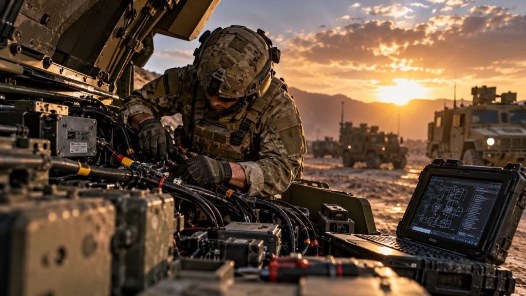
A military vehicle can pass every mechanical inspection and still sit idle because it will not start, will not hold a charge, or throws a fault that nobody can reproduce. Electrical systems sit behind starting and charging, lighting and instruments, engine and transmission control, braking electronics where fitted, communications, navigation, sensors, heating and ventilation, auxiliary equipment and, on some platforms, weapon or mission system interfaces. All of it depends on a power distribution network that must keep working in conditions its designers could not fully control.
Electrical faults are also awkward to diagnose. Vibration, corrosion, temperature, water ingress, poor grounding, connector damage and earlier repairs act on one another, so a fault that appears under load or in wet weather may disappear on the workshop bench.
Why Military Vehicle Electrical Systems Are Especially Vulnerable
Many military ground vehicles use a nominal 28 V DC electrical system. MIL-STD-1275 describes the voltage characteristics, including spikes, surges and reverse polarity, that equipment connected to such a system is expected to withstand. It applies at the input terminals of the equipment, not to the vehicle’s power system as a whole, and it does not mean that every platform runs on 28 V. Nominal voltage is one of the first facts to confirm from the vehicle documentation.
The physical environment is the other half of the problem. Depending on the vehicle and mission, harnesses, connectors and batteries may face vibration and shock, dust, mud, water, humidity, salt, temperature extremes, engine compartment heat, long storage, heavy loads, field repairs, repeated equipment disconnection and add on communications or mission equipment the original design never anticipated. No vehicle sees all of these. The trouble comes from combinations: vibration loosens a terminal, moisture finds the gap, corrosion raises resistance, and the resistance produces heat.
This article does not rank failure causes. Fleet wide failure data is platform specific and rarely published, and an IEEE review of power disturbances in low voltage mobile systems found no comprehensive survey for military combat vehicles. The sections below therefore describe frequently encountered failure areas, not a league table. AB Defence’s article on failure prone components in Oshkosh tactical vehicles shows how thin public evidence can be even for one platform family.
1. Battery Failures and Low Voltage Problems
Batteries fail through ageing, deep discharge, extended storage, loose or corroded terminals, poor connections between batteries, incorrect charging, internal faults and temperature extremes. A lead acid battery self discharges even when the vehicle is parked, and one left discharged or partly discharged develops lead sulfate on its plates. Early sulfation can be reversed with proper charging; prolonged neglect makes recovery much harder. Parasitic drain from connected equipment speeds the process.
A battery can show an acceptable resting voltage and still collapse when the starter demands current. Voltage alone says little about internal condition. Testing should follow the battery manufacturer’s and vehicle’s procedure, which normally means a load test or conductance test on a battery that has first been fully charged. Replacement batteries must match the vehicle’s documented requirements; no universal specification exists, so none is given here.
2. Alternator and Charging System Problems
Alternators age like any rotating machine. The usual failure areas are bearings, the voltage regulator, rectifier diodes, brushes and slip rings where fitted, and the drive belt and tensioner on belt driven units. Heat and contamination shorten life, and the alternator is often blamed for faults that lie elsewhere. DENSO’s aftermarket guidance notes that poor wiring or ground contact raises resistance and reduces charging current, that a loose battery cable can cause intermittent charging and a discoloured or melted output stud, and that high resistance between the alternator output and the battery can burn out diodes. Reverse polarity is another recognised cause of diode failure.
Symptoms include low charging voltage, battery warning indications, slow battery recovery, repeated battery replacement, fluctuating lights and unstable electronics. Correct charging voltage depends on the electrical system and OEM specification, so the vehicle manual gives the figure. A vehicle that keeps consuming batteries needs its charging system and cables checked before another battery is ordered.
3. Starter Motor and Starting Circuit Failures
Starting problems come from solenoids, worn brushes and contacts, internal motor wear, damaged cables, high resistance terminals, poor grounds, a weak battery, or relay and control circuit faults. Slow cranking is not proof of a defective starter. Fluke’s guidance on starter circuits points out that slow or intermittent starting often indicates excessive resistance in the circuit, and that measuring voltage drop during cranking, on both the positive and the ground side, shows where the loss occurs. US military HMMWV troubleshooting material follows the same logic: load test the batteries, check voltage drop across the cables, then check the starter ground. Acceptable limits come from that vehicle’s manual.
4. Wiring Harness Damage
Harness faults are frequently mechanical in origin. Typical causes include chafing, abrasion, crushing, poor routing, heat damage, exposure to oil, fuel and other fluids where leaks occur (see AB Defence’s article on hydraulic system failures), vibration, unsuitable cable ties or clamps, earlier field repairs, rodent damage on stored vehicles, water ingress and damaged insulation.
Intermittent harness faults are hard to find because the damage only matters at certain moments: worn insulation may short only when vibration moves the wire, and a conductor with a few intact strands may pass a light test and fail under load. General inspection points include areas near engine mounts, chassis to body transitions, hinged panels, sharp brackets, high temperature zones, suspension travel areas and, where fitted, cab tilt points. Routing differs from vehicle to vehicle, so the harness drawings in the manual should guide the inspection.
5. Connector and Terminal Failures
Connector problems include corrosion, bent or recessed pins, loose terminals, damaged seals, broken locking tabs, moisture ingress, incorrect mating, poor crimping and improper repair terminals. Fretting deserves particular mention. Small repeated movements between mated contacts wear the surface and oxidise the debris, which raises contact resistance. Published research treats fretting as a major failure mechanism under vibration, and TE Connectivity calls it the traditional failure mode of tin plated contacts.
Appearance does not prove integrity. A connector can look clean and still add resistance, so suspect circuits should be tested under load. Repairs should follow the connector manufacturer’s or OEM’s documented terminal, tooling and sealing procedure. When replacing any connector or terminal, match the connector family, pin count, keying, seal system, terminal size, wire gauge, current capacity and environmental rating. Terminals in sealed families are sized for specific wire ranges, so one that fits the housing may still be wrong for the cable.
6. Grounding and Voltage Drop Problems
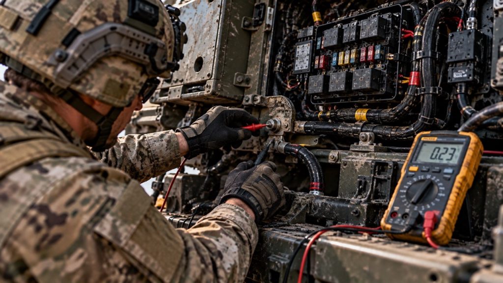
Every current path has a return half, and bad grounding is a recurring cause of faults that resist diagnosis. Problem areas include chassis grounds, engine-to-chassis bonding, battery ground cables, ground studs, corrosion, loose fasteners, paint on contact surfaces, broken ground straps and high resistance joints.
A continuity check passes only a tiny test current, so a corroded joint or a cable with a few remaining strands can show continuity and still fail when the circuit is loaded. Voltage drop testing measures the loss across part of a circuit while current is actually flowing. Fluke recommends testing both the positive and ground sides and recording the results, since the data is repeatable and useful for trend tracking.
7. Fuse, Circuit Breaker, Relay and Power Distribution Failures
Typical problems are blown fuses, incorrect fuse replacement, worn relay contacts, relay coil faults, corroded fuse box terminals, loose connections, overheating, moisture intrusion and, where fitted, power distribution module faults. Littelfuse defines overfusing as fitting a fuse rated higher than the circuit and explains that a blown fuse is doing its job.
Never replace a fuse with a higher rating unless the vehicle documentation explicitly authorises it. A fuse that blows repeatedly points to an underlying fault that must be diagnosed, not masked. The same applies to circuit breakers: protection devices are not to be bypassed.
8. Sensors, Actuators and Electronic Control Modules
Electrical faults affect engine and transmission sensors, wheel speed sensors where fitted, pressure and temperature sensors, solenoids, actuators, control modules and electronic powertrain components. A diagnostic trouble code identifies the circuit that reported a problem; it does not always prove the named component has failed. Upstream causes include wiring, reference voltage, ground, connector condition, power supply, network wiring and mechanical faults.
OEM service documentation from at least one passenger car manufacturer tells technicians to recheck the wiring diagram, grounds and power supply before condemning a control module, and the principle carries over to military electronics. US Army Reserve JLTV training, for example, pairs on board diagnostics with physical faults such as damaged harnesses and blown fuses. Communication architectures differ between vehicles, so no particular network should be assumed without documentation.
9. Water, Moisture and Corrosion
Water can affect connectors, junction boxes, fuse boxes, control modules, battery terminals, harness splices and grounds. Galvanic corrosion needs three things: two dissimilar metals, an electrolyte such as moisture or salt spray, and an electrical path between them. Salt accelerates the process, so coastal or marine operation may raise exposure, depending on each vehicle’s history.
Seals, boots, grommets and enclosure integrity decide how much moisture reaches the metal. A damaged seal is a leak path, and leak paths can wick moisture inward. Seal inspection belongs in any connector or junction box repair.
10. Vibration, Shock, Mechanical Stress and Heat
Vibration causes connector fretting, broken conductors, loosening terminals, relay problems, solder joint damage in some electronics, harness chafing and battery connection problems. Vibration environments vary by vehicle and mission, and compliance with a particular military standard should not be assumed unless the documentation confirms it.
Heat comes from engine bay temperature, routing close to hot components, overloaded circuits, high resistance connections, alternator operation, overheating relays and fuse boxes, and damaged insulation. A high resistance connection dissipates power as heat whenever current flows through it. Thermal imaging can help locate a hot connection, but it is an aid, not a substitute for electrical testing. After an overheating event, adjacent circuits should be inspected too. Engine bay heat is also affected by cooling system failures.
11. Improper Repairs and Incorrect Spare Parts
Many electrical problems begin with the repair. Common errors: the wrong connector or terminal, undersized cable, an incorrect relay or fuse, the wrong alternator, starter or battery type, a non compatible sensor, an incorrect control unit, an unverified cross-reference, improvised splices and unsupported modifications.
Visually similar electrical parts may differ in voltage rating, current rating, connector pinout, communication protocol, mounting arrangement, calibration, software or protection rating.
How to Diagnose Military Vehicle Electrical Problems
A fixed sequence prevents random part replacement. Adapt the order below to the vehicle’s manual. High current circuits and live work call for qualified personnel and the precautions in the applicable documentation.
- Confirm the complaint and the conditions in which it occurs.
- Check the technical documentation, wiring diagram and any open service bulletins.
- Verify battery condition and system voltage.
- Inspect terminals and grounds.
- Inspect fuses and power distribution.
- Inspect harnesses and connectors visually.
- Perform voltage drop tests on the suspect circuits under load.
- Check the charging and starting systems.
- Read diagnostic codes where the vehicle supports them.
- Use the wiring diagram to isolate the circuit.
- Test the suspected component to the OEM procedure.
- Verify the repair under operating conditions.
Systematic diagnosis protects the spares budget and avoids the second failure that follows a part swapped without cause.
Critical Electrical Spare Parts for Military Vehicle Fleets
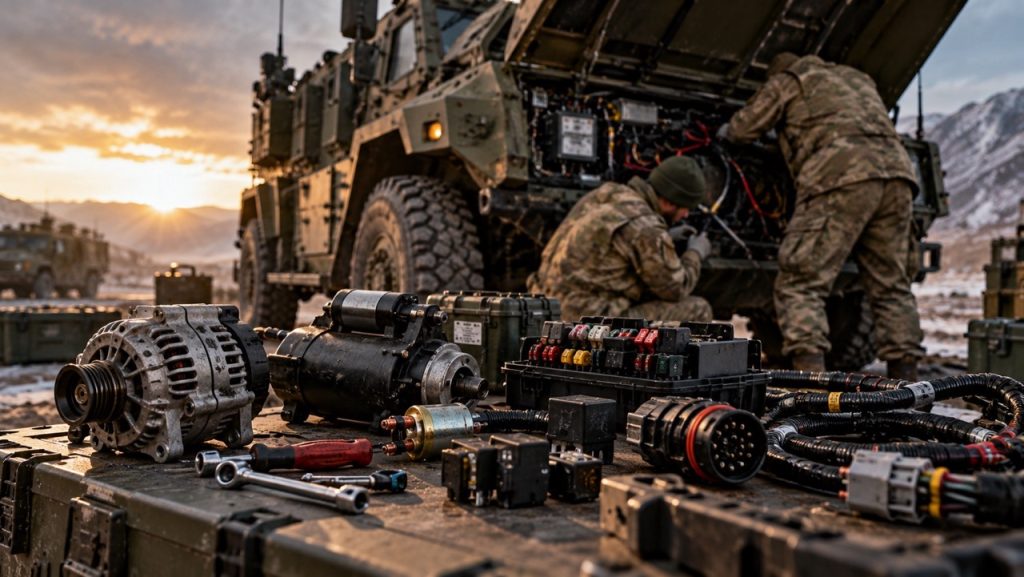
A practical electrical spares strategy usually draws on these categories of electrical and electronic spare parts:
- Power and starting: batteries, starter motors, alternators and, where separately serviceable, voltage regulators.
- Protection and switching: relays, fuses, circuit breakers, switches, and ignition or start switches where applicable.
- Conductors and connections: battery cables, ground straps, approved terminals, connector bodies and seals, wiring repair kits and harness sections.
- Sensing and actuation: sensors and solenoids.
- Lighting: lamps and lighting components.
- Distribution and control: power-distribution modules, junction boxes and, where the fleet support strategy requires them, control modules.
No fleet should stock everything listed. The right holding depends on fleet size, vehicle model, mission, operating environment, failure history, lead time, parts criticality, local repair capability, OEM support and obsolescence risk. Fuses, seals and terminals call for a different approach from long lead control modules.
How to Identify the Correct Electrical Spare Part Before Ordering
Do not identify an electrical spare part only from appearance. A starter, alternator or relay that looks right may be wrong in ways a photograph cannot show. AB Defence’s detailed guide explains how to identify the correct military vehicle spare part before ordering; for electrical items, the checks below matter most.
- Vehicle make, model, variant, production year, and serial or chassis number.
- OEM part number, exactly as written, and the NSN where one is officially assigned and verified. An NSN is a 13-digit NATO Stock Number issued through the NATO Codification System, and the NCAGE code identifies the manufacturer behind a part number.
- Technical manual or parts catalogue reference, including figure and item number.
- Voltage, current or power rating, and fuse or relay specification.
- Connector type, pin configuration, mounting arrangement, cable length and wire gauge.
- Sensor type and, where documented, the communication protocol.
- Software or calibration requirements for electronic modules.
- Environmental sealing requirements.
Interchangeability is a documented engineering decision, not an observation. A wrong assumption can cost days out of service, or a part that fits and then fails.
Preventive Maintenance Practices That Reduce Electrical Failures
Prevention largely means inspecting the same things regularly and recording what is found:
- Routine battery inspection and battery state monitoring.
- Terminal and ground maintenance, with inspection of ground points and straps.
- Inspection of harness routing, connectors, seals and grommets.
- Charging system tests, and starter circuit voltage drop tests where indicated.
- Fuse box inspection and corrosion inspection.
- Inspection after deep water or mud exposure where the applicable manual requires it.
- Correct storage procedures, including battery charging during long term storage.
- Documentation of recurring faults, so repeat failures show up as a pattern.
Intervals and procedures must come from the applicable technical manual and OEM documentation. None are proposed here.
Electrical Troubleshooting: Common Mistakes to Avoid
- Replacing batteries repeatedly without checking the charging system.
- Replacing a starter without voltage drop testing.
- Replacing a sensor only because of a fault code.
- Ignoring grounding problems.
- Installing a higher rated fuse.
- Using unsealed connectors in exposed areas.
- Making unsupported harness splices.
- Ordering electrical parts by appearance.
- Skipping adjacent circuits after an overheating event.
- Ignoring parasitic draw during vehicle storage.
- Assuming every vehicle variant uses the same component.
Conclusion
Electrical reliability decides whether a mechanically sound vehicle is actually available. The failures above are mostly ordinary ones: ageing batteries, resistance in cables and grounds, damaged harnesses, worn connectors and seals, and repairs made with the wrong part. They are manageable when diagnosis is systematic, preventive checks are recorded, and parts are identified against the vehicle’s own documentation before ordering. Platform specific patterns, such as those described for military Unimog vehicles, matter as much as the general principles.
AB Defence supports military vehicle fleets with spare parts identification, sourcing and sustainment for land platforms. Teams working through an electrical parts requirement can send vehicle configuration details and part identifiers through the AB Defence contact page.
Related Military Spare Parts Categories, Vehicle Platforms & Technical Guides
Explore AB Defence’s NATO-codified (NSN) and genuine OEM spare parts catalog, platform technical specifications, and sustainment engineering guides related to this article:
Stocked Spare Parts Categories (NSN & OEM Catalog)
- Military Brake Calipers, Master Cylinders & Hydraulic Systems (103 stocked parts)
- Electrical, Electronic & Vision Systems for Military Vehicles (250 stocked parts)
- Military Pneumatic Air Fittings, Brake Valves & Compressors (115 stocked parts)
- Military Portal Axles, Differentials & Drive Shafts (107 stocked parts)
- Military Cab, Armor Body Panels, Mirrors & Structural Hardware (130 stocked parts)
- Full NATO NSN & OEM Spare Parts Catalog (16,760+ Parts)
Compatible Vehicle Platforms & System Hubs
- Brake & Suspension Systems
- Hydraulics & Mechanical Components
- Electrical, Electronic & Vision Systems
- Body, Panel & Gasket Solutions
- Tactical Wheeled Vehicles
- Request a B2B Quotation (RFQ) & Technical Support
Related Military Engineering & Sustainment Articles
- Military Brake System Failures: Causes, Risks and Maintenance Priorities
- Military Vehicle Hydraulic System Failures: Causes, Maintenance and Critical Spare Parts
- Armored Vehicle Suspension Failures: 6 Warning Signs Maintenance Teams Should Never Ignore
- 8 Components Most Frequently Replaced in Armored Military Vehicles